
On-Premises Deployment High Availability and Disaster Recovery
When you run Mule runtime engine on servers that you manage, you build high availability (HA) and disaster recovery (DR) yourself. You achieve HA by clustering Mule runtime instances so that another node takes over when one fails, and you choose a standby topology that matches your SLA. You own DR under a shared-responsibility model: because you control the infrastructure, you back up, restore, and recover it with your own tooling, while MuleSoft provides the runtime clustering capabilities and control-plane availability through Anypoint Platform.
For an overview of HA and DR across all Mule deployment models, see High Availability and Disaster Recovery.
High Availability Versus Disaster Recovery
High availability (HA) measures a system’s ability to remain accessible when a component fails. On self-managed servers, you achieve HA by clustering and load balancing Mule runtime nodes, so that another node takes over when one fails.
Disaster recovery (DR) restores a system to an acceptable previous state after a natural or man-made disaster, such as flooding, power failures, server failures, or misconfigurations.
Both strategies increase availability but differ in scope: on-premises, HA keeps your application serving requests when a node in the cluster fails with no loss of service, whereas DR restores service and data after an infrastructure disaster and usually incurs a brief loss of service while the DR plan runs.
Two measurable objectives drive your DR plan:
- Recovery Time Objective (RTO)
-
The maximum downtime a business tolerates. RTO is the time the system takes to recover after a disruption.
- Recovery Point Objective (RPO)
-
The maximum data loss a business accepts after a disaster. RPO drives how often you back up data.
High Availability in On-Premises Deployments
You achieve high availability on self-managed servers by clustering and load balancing Mule runtime nodes. Depending on your SLA, you choose a standby topology and a deployment architecture that meet your availability and fault-tolerance requirements.
- Clustering and failover
-
You can deploy Mule runtime engine in many topologies to support your HA and DR strategies. One common method, high-availability clustering, gives Mule basic failover capability. When the primary Mule runtime becomes unavailable—because of a fatal JVM or hardware failure, or because you take it offline for maintenance—a backup Mule runtime immediately takes over as the primary node and resumes processing where the failed instance stopped. After you recover the failed Mule runtime server and bring it back online, that server automatically becomes the backup node.
- Distributed memory
-
A distributed memory store makes seamless failover possible by sharing all transient state across clustered Mule runtimes, including SEDA service event queues and in-memory message queues.
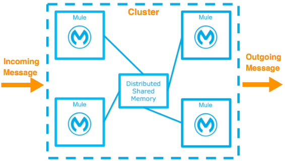
As you build your Mule application, think critically about how to architect it for the availability, fault tolerance, and performance you need.
High Availability Options
You achieve high availability by clustering and load balancing nodes. Depending on your SLA, Mule supports four HA options:
| These options often pair with a disaster recovery strategy. |
Cold Standby
| Diagram | Description | Downtime |
|---|---|---|
|
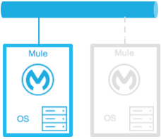
You install and configure the Mule environment but leave one or more operating systems stopped—for example, as a backup of a production system or virtual machine. You start the operating system and the Mule runtime after you detect an outage. |
Some. Covers the time to start the environment and route traffic. |
Warm Standby
| Diagram | Description | Downtime |
|---|---|---|
|
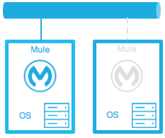
You install and configure the Mule environment and run the operating systems but leave the Mule runtimes stopped. You start the Mule runtime after you detect an outage. |
Little. Covers the time for the Mule runtime instances to start and route traffic to the environment. |
Hot Standby - Active-Passive
| Diagram | Description | Downtime |
|---|---|---|
|
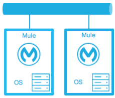
You install, configure, and fully run the Mule environment, but it doesn’t process requests until you detect an outage. |
Minimal to none. Covers the time to route traffic to the environment. |
Active-Active
| Diagram | Description | Downtime |
|---|---|---|
|
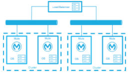
Load-balanced clustered environments: Two or more fully operational Mule environments run at the same time, each with its own cluster, and the load balancer distributes traffic across all of them. |
None. The service experiences no downtime. |
|
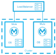
Load-balanced single clustered environment: Two or more Mule environments belong to the same cluster. This scenario requires network latency between environments to stay below 10 ms. |
None. The service experiences no downtime. |
On-Premises Deployment Models
You size your on-premises architecture to meet your SLA. Mule supports three common deployment models:
Active-Active Clustering Deployment Model
Two nodes in a clustered or load-balanced environment can plausibly support 1,500 TPS with 1-second responses, which meets the normal SLA. If one node fails, the service degrades but still handles 700 TPS with 1-second responses—well above the agreed acceptable impact—so the failure doesn’t breach the SLA.
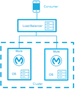
Distribute the load evenly across multiple Mule nodes:
-
All nodes offer the same capabilities.
-
All nodes stay active at the same time.
Costs
Costs vary with your SLA requirements. This model needs two nodes to meet the SLA. If the acceptable service impact rises to match normal operations, the environment needs at least three nodes to absorb a single node failure. High-probability failure scenarios can require even more nodes.
Active-Active Clustering Fault Tolerance Deployment Model
Fault tolerance means a failure within the system doesn’t affect the service at all. It differs from high availability, which tolerates some service impact and downtime.
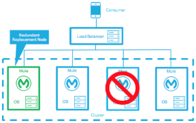
Fault tolerance differs from high availability by adding resources that let an application keep running—without interruption—after a component fails. Fault-tolerant environments cost more than highly available environments.
The degree of fault tolerance you need depends on the probability of system failures. Take the earlier SLA example and raise the minimum acceptable service impact to match the normal operation requirement.
The new SLA now requires the system to handle 1,000 transactions per second with 1-second response times, zero downtime, and zero service impact.
If the probability of losing more than one node stays low, the architecture needs just three nodes. If that probability rises above what you accept, the architecture needs more than three nodes to absorb multiple failures.
Costs
This model costs more because it requires the redundancy to meet the defined SLA.
Zero Downtime Deployment Model
This model lets you change the environment—including upgrading the infrastructure and the applications that run on it—without breaching your SLAs. Zero-downtime deployments typically use a side-by-side approach, where the old and new environments coexist briefly. An in-place deployment, by contrast, can reduce capacity or cause complete downtime.
Gartner defines continuous operations as "those characteristics of a data-processing system that reduce or eliminate the need for planned downtime, such as scheduled maintenance. One element of 24-hour-a-day, seven-day-a-week operation".
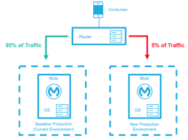
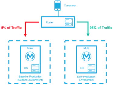
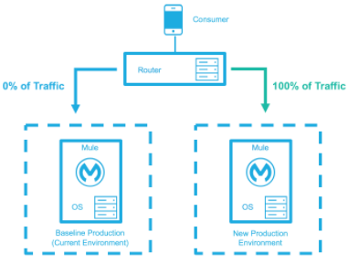
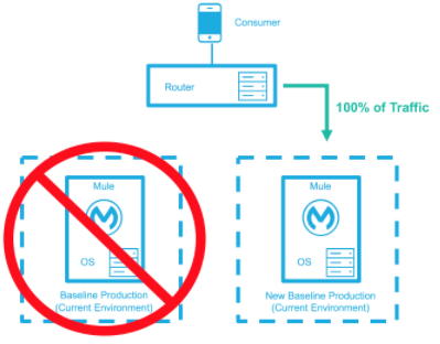
The baseline production environment is your current operating environment. You create a new environment with the changes—upgraded runtimes, new configurations, and new applications. A small percentage of traffic flows to the new environment and increases as your confidence grows. The baseline environment keeps serving traffic until the new environment handles 100 percent of the traffic. After the new environment accepts all traffic, it becomes the new baseline production environment, and the previous baseline terminates.
This example assumes that each environment uses the same number of Mule runtimes and cores, but the new environment can use more or fewer.
| Deployment Step | Diagram |
|---|---|
You deploy the new production environment and route a small percentage of traffic to it. |
|
Your confidence in the new environment grows, and you route more traffic to it. |
|
You route all traffic to the new environment. |
|
You promote the new environment to baseline production and terminate the previous baseline. |
|
Costs
This method can temporarily add capacity to the service for a few minutes, hours, or days.
Disaster Recovery in On-Premises Deployments
Because you control the infrastructure, you own disaster recovery for on-premises deployments. You back up your servers, applications, and data, and you bring backup infrastructure online to meet your recovery objectives when your primary environment fails.
- Standby topologies
-
Use a cold, warm, or hot standby topology to meet your RTO and RPO. A hot standby minimizes downtime but costs the most, whereas a cold standby costs the least but takes longest to recover.
- Backups
-
Back up Mule applications, runtime configurations, and application data to external storage outside your primary environment. Schedule backups often enough to meet your RPO.
- Anypoint configuration
-
Back up your platform configurations—such as connections and properties—with the Anypoint CLI or Anypoint Platform APIs.
- MuleSoft responsibility
-
MuleSoft keeps the Anypoint Platform control plane available across multiple availability zones. The control plane stores only operational metadata and configuration, not your business data.
Considerations and Limitations
Account for these factors when you design a clustered on-premises topology:
- Network latency
-
Clustering across availability zones or regions can degrade performance because of network latency. A single clustered environment that spans locations requires network latency between nodes to stay below 10 ms. Where possible, place cluster nodes on the same subnet or availability zone.
- Simultaneous node restarts
-
Don’t restart multiple cluster nodes at the same time, such as during operating system patching. Concurrent restarts can trigger cluster-membership eviction and take applications offline.
- Sequential deployment staging
-
When you deploy an application to an on-premises Mule cluster through Runtime Manager, Runtime Manager stages deployment artifacts to cluster nodes sequentially. Sequential staging doesn’t guarantee that the application starts on one node before startup begins on another. Application startup and readiness across cluster nodes follow no fixed order and can overlap.
- Cost trade-offs
-
Higher availability and fault tolerance require more nodes and infrastructure. Size your architecture to the SLA you must meet, rather than to the maximum possible resilience.
Best Practices
Follow these design principles for high availability and disaster recovery on self-managed servers:
-
Keep your integrations stateless, and externalize state to an external store, such as a database or a messaging queue.
-
Run identical Mule runtime, Runtime Manager agent, and Java versions on all cluster nodes.
-
Choose a standby topology and node count that meet your SLA rather than the maximum possible resilience.
-
Schedule cluster changes during maintenance windows.
-
Test your failover and restore procedures regularly.