
TRADACOMS EDI Connector 3.0
TRADACOMS EDI Connector 3.0
Convert TRADACOMS transmissions to and from DataWeave-compatible representations by using lists and maps.
Supported TRADACOMS files and versions are:
-
ACKMNT:4
-
AVLDET:4
-
CORDER:6
-
CRAINF:3
-
CREDIT:9
-
CUSINF:8
-
DELIVR:9
-
DLCDET:5
-
DRAINF:3
-
EXCINF:3
-
GENRAL:3
-
INVOIC:9
-
LPRDET:2
-
ORDERS:9
-
PAYINF:3
-
PICKER:4
-
PPRDET:2
-
PRIINF:8
-
PROINF:8
-
SADDET:3
-
SNPSTS:3
-
SRMINF:9
-
UCNDET:3
-
UPLIFT:4
-
UTLBIL:3
Before You Begin
To use TRADACOMS EDI Connector 3.0, you must be familiar with:
-
Anypoint Connectors
-
Mule runtime engine (Mule)
-
Elements and global elements in a Mule flow
-
Mule apps in Anypoint Studio or Anypoint Code Builder
-
TRADACOMS EDI Connector
To use TRADACOMS EDI Connector 3.0 in a production environment, you must have:
-
A MuleSoft license for Anypoint B2B (contact your Salesforce account executive about purchasing a license)
-
Anypoint Studio or Anypoint Code Builder
What’s New in TRADACOMS EDI Connector 3.0
-
TRADACOMS EDI Connector 3.x supports newer Mule runtime versions and doesn’t include functional changes.
-
The connector supports messages from multiple versions of the standards. Version information in the message header (UNH segment) identifies the standard version, and the message identifier determines the schema.
-
Identification parameters aren’t used for the Read and Write operations. Configure all parameter values in the message data that’s passed to the Write operation.
-
If you don’t reference schemas in the configuration, the connector looks up the standard version of the schema for each message from the classpath and uses that schema for reading and writing. When this occurs, metadata isn’t available for the message data structure because the actual messages are unknown at design time.
Install This Connector in Anypoint Studio 7
-
In Anypoint Studio, click the Exchange icon in the Studio taskbar.
-
Click Login in Anypoint Exchange.
-
Search for the connector and click Install.
-
Follow the prompts to install the connector.
When Studio has an update, a message appears in the lower-right corner. Click the message to install the update.
Change the default Anypoint configuration to use TRADACOMS EDI Connector 3.0.
Create Schemas
If your implementation conventions differ from the standard, create schemas that describe your messages according to your implementation. Standard versions of the schemas for all defined TRADACOM files are included in the distribution.
EDI Schema Language
TRADACOMS EDI Connector uses a YAML format called ESL (for EDI Schema Language) to represent EDI schemas. ESLs define the structure of EDI messages in terms of structures (messages, in TRADACOMS terminology), groups, segments, composites, and elements.
ESL definitions for TRADACOMS differ from other EDI formats, particularly when you work with the TRADACOMS concepts of files and messages. Each file format defined by TRADACOMS represents data for a specific use. The file format is broken down into several message components, and one message component is allowed to repeat. Each message component is broken down into segments and groups of segments, some of which can also be repeated.
In ESL terms, each TRADACOMS file format is represented by a schema definition. The supplied ESL schemas use the generic name for the file, which is the same as that of the repeating detail message. For example, the Price Information File structure is given by the PRIINF.esl schema definition. Within the file schema, each component message type is defined as a structure. The order of component messages within a file is given by the class value, which must be a string consisting of a single digit. The value '1' identifies the header message, the value '2' identifies the repeating detail message, and all higher values are successive messages within the file.
To customize the TRADACOMS schema definitions to suit your data, define an overlay schema. An overlay schema is a special form of ESL that modifies a base schema, such as a TRADACOMS INVOIC schema, with your specific conventions. You don’t need an overlay schema if you’re using the structure defined by the standard.
Define your own schemas from scratch, or copy and edit a base TRADACOMS schema definition to suit your data.
|
YAML uses a combination of lists and sets of key-value pairs. The order of values isn’t important, as long as the required items are present. Use quotes (either single or double quotes) around values that consist of digits but must be interpreted as strings, because otherwise the YAML parser treats the values as numbers. Indentation shows the nesting of lists. For readability, the ESL structures shown here define all simple key-value pairs before any lists that are part of the same definition. |
Define Your Implementation Convention with an Overlay Schema
To specify a schema according to your implementation convention:
-
Create an overlay schema that imports the base schema you want to customize, such as TRADACOMS INVOIC.
-
Customize the overall structure for segment usage, positions, groups, and counts.
-
Customize segments, including usage and counts.
Overlay schemas list only changes instead of providing all the details of a schema structure. They specify how to use implementation conventions with a particular trading partner to extend and customize the standard.
This example overlay schema modifies the basic TRADACOMS INVOIC file definition. The example adds a REBILL message at version 6 to the file. The REBILL message follows all existing messages (class value '5'), because an INVOIC file normally has four message components.
form: TRADACOMS
version: 'INVOIC9'
imports: [ '/tradacoms/INVOIC.esl' ]
structures:
- id: 'REBILL'
  name: 'REBILL:6'
  class: '5'
  data:
  - { idRef: 'MHD', usage: M }
  - { idRef: 'RBL', usage: M }
  - { idRef: 'MTR', usage: M }
segments:
- id: 'RBL'
  name: 'REBILLING DETAILS'
  values:
  - { id: 'RBLA', name: 'Rebill From Field', usage: M, type: char, minLength: 1, maxLength: 14 }
  - { id: 'RBLB', name: 'Rebill To Field', usage: M, type: char, minLength: 1, maxLength: 14 }
  - { idRef: 'PAI', position: '0040', usage: U }
Structure Overlay
A structure overlay details modifications to the base schema definition of a TRADACOMS message. These modifications often take the form of marking segments or groups in the base definition as unused, but any usage or repetition count change is allowed.
This structure overlay example:
structures:
- idRef: 'INVFIL'
  data:
  - { idRef: 'FDT', position: '07', usage: M }
  - { idRef: 'ACD', position: '08', usage: M }
These modifications specify that the FDT (at position 7) and ACD (at position 8) segments are required in each INVFIL message (usage: M for mandatory). With this overlay, errors are reported if either the FDT or ACD segment isn’t present in a message.
The key-value pairs at the structure level are:
| Key | Description |
|---|---|
idRef |
The ID for the message being modified. |
class |
The position of the message within a file (optional). |
name |
The message name and version (optional). |
data |
List of segment and group modifications within the structure (optional, each is used only when there are modifications to that section). |
Each item in the list of structure data components is either a segment reference or a group definition. Both are shown here by using a compact YAML syntax where the values for each reference are given as comma-separated key-value pairs enclosed in curly braces.
The values are:
| Key | Description |
|---|---|
idRef |
The referenced segment ID. This is optional and verified if provided, but otherwise ignored. The position value uniquely identifies segments within the section. |
position |
The segment position within the message section. |
usage |
Usage code, which can be |
count |
Maximum repetition count value, which can be a number or the special value |
The values in a group definition are:
| Key | Description |
|---|---|
groupIdRef |
The referenced group ID. This key is optional and verified if provided, but otherwise ignored. The position value uniquely identifies a group within a section. |
position |
The segment position within the message section. |
usage |
Usage code, which can be |
count |
Maximum repetition count value, which can be a number or the special value |
items |
List of segments (and potentially nested groups) that make up the group. |
Segment Overlay
A segment overlay details modifications to the base schema definition. These modifications often take the form of marking elements or composites in the base definition as unused, but any usage or repetition count change is allowed.
These segment overlay examples:
structures:
- idRef: 'INVFIL'
  data:
  - { idRef: 'FDT', position: '07' }
segments:
- idRef: 'FDT'
  values:
  - { position: 1, usage: M }
  - { position: 2, usage: M }
This example modifies the base definition for the FDT segment. Both values defined in the segment become required fields. They’re optional in the base definition.
Segment modifications affect only structures that are included in the overlay with explicit references to the modified segments. That’s why the overlay must include the FDT segment reference in the INVFIL message structure. Include the reference even when usage and repetition count don’t change.
The key-value pairs in a segment overlay are:
| Key | Description |
|---|---|
idRef |
Segment identifier. |
trim |
Trim position in segment, meaning all values from this point on are marked as unused (optional). |
values |
List of individual value modifications. |
The values list references values in the segment by position. The values for these references are:
| Key | Description |
|---|---|
position |
The value position within the segment. |
name |
The name of the value in the segment (optional, base definition value used if not specified). |
usage |
Usage code, which can be |
Determine the TRADACOMS Schema Location
To use the connector, you must know the locations of the schemas
in your project. If you’re using out-of-the-box TRADACOMS schemas and
not customizing anything, the schema location follows the
/tradacoms/{file}.esl pattern. For the ORDERS file, your schema location is /tradacoms/ORDERS.esl.
If you’re using one or more custom schemas, put these under
a directory in src/main/app and refer to the location by using ${app.home}.
For example, if you put your CREDIT schema (either overlay or full) under src/main/app/mypartner/CREDIT.esl,
your schema location is ${app.home}/mypartner/CREDIT.esl.
Mule runtime engine (Mule) automatically checks src/main/app for any locations
that contain the ${app.home} value.
To Create a Mule Project in Anypoint Studio 7
After you install the connector and customize your schemas, start using the connector. Create separate configurations for each implementation convention.
-
At the base of the canvas, click the Global Elements tab, and then click Create.
-
In the Choose Global Type wizard, locate and select TRADACOMS EDI: Configuration, and then click OK.
-
To save the global connector configurations, click OK.
-
Return to the Message Flow tab in Studio.
Set each tab in the Global Element Properties window as described in these sections.
General Tab
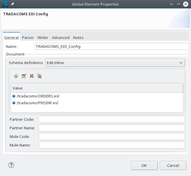
Use the General tab to configure settings for reading and writing TRADACOMS messages, including identification information used in the STX segment:
-
Manually create or edit the list of schema definitions for the message structures to be used.
-
Partner Sender/Recipient Code (STX FROM or UNTO Code)
-
Partner Sender/Recipient Name (STX FROM or UNTO Name)
-
Mule Application Sender/Recipient Code (STX FROM or UNTO Code)
-
Mule Application Sender/Recipient Name (STX FROM or UNTO Name)
All these identification values are optional. If any are configured, the values are verified when reading an input transmission and used as the defaults when writing an output transmission if no value is specified in the output data.
Parser Tab
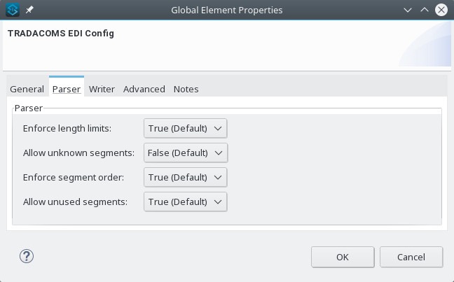
Set these options to control parser validation of received messages:
-
Enforce minimum and maximum lengths for receive values.
-
Allow unknown segments in a message.
-
Allow segments marked as
Unusedin a message. -
Enforce segment order in a message.
Writer Tab
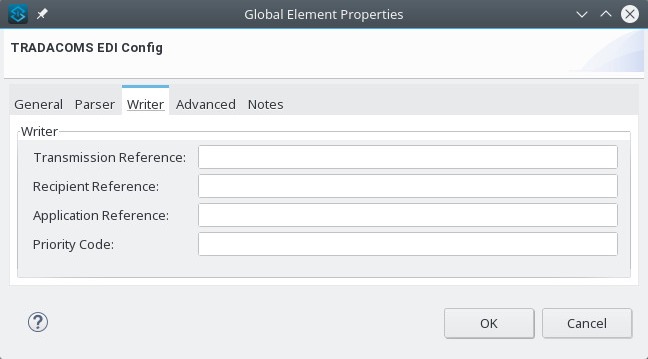
Settings for writing messages:
-
Default Sender’s Transmission Reference used when writing a transmission
-
Default Recipient’s Transmission Reference used when writing a transmission
-
Default Application Reference used when writing a transmission
-
Default Transmission Priority Code used when writing a transmission
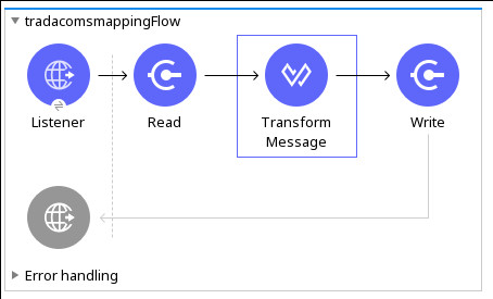
TRADACOMS Studio Example
Load this flow in the XML for a project.
<?xml version="1.0" encoding="UTF-8"?>

<mule xmlns:ee="http://www.mulesoft.org/schema/mule/ee/core"
xmlns:tradacoms="http://www.mulesoft.org/schema/mule/tradacoms"
	xmlns:http="http://www.mulesoft.org/schema/mule/http"
	xmlns="http://www.mulesoft.org/schema/mule/core"
	xmlns:doc="http://www.mulesoft.org/schema/mule/documentation"
	xmlns:xsi="http://www.w3.org/2001/XMLSchema-instance"
	xsi:schemaLocation="http://www.mulesoft.org/schema/mule/core http://www.mulesoft.org/schema/mule/core/current/mule.xsd
http://www.mulesoft.org/schema/mule/http
http://www.mulesoft.org/schema/mule/http/current/mule-http.xsd
http://www.mulesoft.org/schema/mule/tradacoms
http://www.mulesoft.org/schema/mule/tradacoms/current/mule-tradacoms.xsd
http://www.mulesoft.org/schema/mule/ee/core
http://www.mulesoft.org/schema/mule/ee/core/current/mule-ee.xsd">
	<http:listener-config name="HTTP_Listener_config" doc:name="HTTP Listener config">
		<http:listener-connection host="localhost" port="8081" />
	</http:listener-config>
	<tradacoms:config name="TRADACOMS_EDI_Config" doc:name="TRADACOMS EDI Config">
		<tradacoms:schemas>
			<tradacoms:schema value="/tradacoms/ORDERS.esl"/>
			<tradacoms:schema value="/tradacoms/PROINF.esl"/>
		</tradacoms:schemas>
	</tradacoms:config>
	<flow name="tradacomsmappingFlow">
		<http:listener doc:name="Listener" config-ref="HTTP_Listener_config" path="/map"/>
		<tradacoms:read doc:name="Read" config-ref="TRADACOMS_EDI_Config"/>
		<ee:transform doc:name="Transform Message">
			<ee:message >
				<ee:set-payload ><![CDATA[%dw 2.0
output application/java
---
{
	STX: payload.STX,
	Id: payload.Id,
	ORDERS: payload.ORDERS
}]]></ee:set-payload>
			</ee:message>
		</ee:transform>
		<tradacoms:write doc:name="Write"/>
	</flow>
</mule>
Configuration Options in XML
Set all Anypoint Studio configuration values directly in XML.
General parameters control both send and receive document handling. All are optional.
| XML Value | Anypoint Studio Option |
|---|---|
schemas=list of values |
List of paths for schemas to be used by the connector. The paths can be for a file system or classpath. |
partnerCode |
Code used to identify the partner. If you specify this value, it’s used both to validate the Transmission Sender Code in received transmissions and to set the Transmission Recipient Code in sent transmissions (if not already specified in map data). If you don’t specify this value, the Transmission Sender Code isn’t checked in received transmissions. |
partnerName |
Name used to identify the partner. If you specify this value, it’s used both to validate the Transmission Sender Name in received transmissions and to set the Transmission Recipient Name in sent transmissions (if not already specified in map data). If you don’t specify this value, the Transmission Sender Name isn’t checked in received transmissions. |
selfCode |
Code used to identify the Mule app. If you specify this value, it’s used both to validate the Transmission Recipient Code in received transmissions and to set the Transmission Sender Code in sent transmissions (if not already specified in map data). If you don’t specify this value, the Transmission Recipient Code isn’t checked in received transmissions. |
selfName |
Name used to identify the Mule app. If you specify this value, it’s used both to validate the Transmission Recipient Name in received transmissions and to set the Transmission Sender Name in sent transmissions (if not already specified in map data). If you don’t specify this value, the Transmission Recipient Name isn’t checked in received transmissions. |
Parser parameters control the parser operation and the types of error conditions that cause receive messages to be rejected. All are optional, with default values as shown.
| XML Value | Visual Studio Option |
|---|---|
enforceLengthLimits="true" |
Enforce minimum and maximum lengths for receive values. |
allowUnknownSegments="false" |
Allow unknown segments in a message. |
allowUnusedSegments="false" |
Allow segments marked as |
enforceSegmentOrder="true" |
Enforce segment order in a message. |
Writer parameters control the writer operation. All are optional.
| XML Value | Visual Studio Option |
|---|---|
sendSenderReference |
Default Sender’s Transmission Reference used when writing a transmission. |
sendRecipientReference |
Default Recipient’s Transmission Reference used when writing a transmission. |
sendApplicationReference |
Default Application Reference used when writing a transmission. |
sendPriorityCode |
Default Transmission Priority Code used when writing a transmission. |
Set Schema Locations
Configure schema locations in the Anypoint Studio XML view.
In Anypoint Studio, click Configuration XML and modify your TRADACOMS EDI configuration to include a list of all the schemas you want to include. Add a <tradacoms:schema> element for each document type:
<tradacoms-edi:config name="TRADACOMS_EDI__Configuration" identKeys="true" doc:name="TRADACOMS EDI: Configuration">
  <tradacoms-edi:schemas>
    <tradacoms:schema value="/tradacoms/ORDERS.esl"/>
  </tradacoms-edi:schemas>
</tradacoms-edi:config>
After you create a global element for your TRADACOMS EDI Connector, configure any schemas and operations.
TRADACOMS Message Structure
Use the connector to read TRADACOMS documents into, or write TRADACOMS documents from, the canonical EDI message structure. This structure is represented as a hierarchy of Java Maps and Lists, which you manipulate by using DataWeave or code. Each transaction has its own structure, as defined in the schemas.
The message contains these keys. Some apply only to either the Read operation or the Write operation, as indicated.
| Key Name | Description |
|---|---|
{File} |
Wrapper for message data, with keys matching the names of the component messages linking to data for those messages. For the repeating detail message of the file (always class |
Errors (read only) |
A list of errors that are associated with the input message. See the TradacomsError structure description in Read and Validate TRADACOMS EDI Messages. |
Id |
File (the name of the TRADACOMS file read). |
STX |
Map of STX segment data from the start of the file. |
Individual messages have their own maps under the file name map, with keys matching the segments of the message. For example, an INVOIC file
has the key 'INVOIC' in the root map, and under that keys for 'INVFIL', 'INVOIC' (the list of data for repeating INVOIC messages),
'VATTLR', and 'INVTLR'. Within the INVTLR map there are keys '01_MHD', '02_TOT', and '03_MTR' for the segments of the
INVTLR message.
Read and Validate TRADACOMS EDI Messages
-
To read a TRADACOMS message, search the palette for TRADACOMS EDI, and drag the TRADACOMS Read operation into a flow.
-
In the properties view, select the connector configuration that you created, and then select the Read operation. This operation reads any byte stream into the structure described by your TRADACOMS schemas.
TRADACOMS EDI Connector validates each message when it reads the message. Message validation includes checking the syntax and content of envelope segments STX and END and the messages in the file. The connector logs, accumulates, and reports errors in TradacomsError instances. It sends all accepted messages (error-free or with non-fatal errors) for processing as part of the output message Map. If any fatal errors are found, no file data is returned, only the error list.
Error data entered in the receive data map uses the TradacomsError class, a read-only JavaBean with these properties:
| Property | Description |
|---|---|
segment |
The zero-based index within the input of the segment causing the error. |
fatal |
Flag for a fatal error, in which case no file data is returned. |
errorText |
Text description of the error. |
The Read operation returns error data as optional lists with the Errors key at the root level of the data structure and at the message level. At the message level, this list contains non-fatal errors encountered during the parsing of that message. At the root level, this list contains both interchange errors and fatal message errors.
Write TRADACOMS EDI Messages
To write an outgoing message, search the palette for TRADACOMS EDI and drag the TRADACOMS Write operation into a flow. Construct an outgoing TRADACOMS EDI message according to the structure defined in TRADACOMS Message Structure for input to the Write operation. If no fatal errors are found in the Write operation, the normal flow continues. Otherwise, the connector throws an exception that describes the error.