HL7 EDI Connector 4.0
Anypoint Connector for HL7 EDI (HL7 EDI Connector) lets you convert HL7 ER7 messages to and from DataWeave-compatible representations using lists and maps.
Release Notes: Release Notes
Exchange: HL7 EDI Connector![]()
Before You Begin
This document assumes that you are familiar with HL7, Mule, Anypoint Connectors, Anypoint Studio, Mule flows, and Mule Global Elements.
See the Release Notes for compatibility information. A link to the release notes is listed in the See Also section of this document.
You must purchase a license for the HL7 EDI Connector to use it in a production environment.
POM File Information
<dependency>
<groupId>com.mulesoft.connectors</groupId>
<artifactId>mule-hl7-extension</artifactId>
<version>4.0.3</version>
<classifier>mule-plugin</classifier>
</dependency>xmlReplace version 4.0.3 for the version you are using. To specify a version, view Anypoint Exchange and click Dependency Snippets.
What’s New in this Connector
The data structures used by the HL7 EDI Connector 4.0.0 differ from those in the 3.x version used with Mule 3.x.
In the 3.x version of the connector, composite components are effectively in-lined at the point of use, so that each individual element nested within the composite component is given a key based on the containing segment and referenced directly from the map representing the segment.
In the 4.x version of the connector each composite component is instead represented by a child map and the values within the composite have keys based on the composite identifier.
This change in structure allows consistent mappings to be used for data in composite components, regardless of the containing segment or position within the segment.
Add the Connector to a Studio Project
Anypoint Studio provides two ways to add the connector to your Studio project: from the Exchange button in the Studio taskbar or from the Mule Palette view.
Add the Connector Using Exchange
-
In Studio, create a Mule project.
-
Click the Exchange icon (X) in the upper-left of the Studio task bar.
-
In Exchange, click Login and supply your Anypoint Platform username and password.
-
In Exchange, search for "HL7".
-
Select the connector and click Add to project.
-
Follow the prompts to install the connector.
Add the Connector in Studio
-
In Studio, create a Mule project.
-
In the Mule Palette view, click (X) Search in Exchange.
-
In Add Modules to Project, type "HL7" in the search field.
-
Click this connector’s name in Available modules.
-
Click Add.
-
Click Finish.
Create Schemas
Create schemas to describe your messages according to your implementation.
EDI Schema Language
The HL7 EDI uses a YAML format called ESL (for EDI Schema Language) to represent EDI schemas. Basic ESLs define the structure of ER7 messages in terms of structures (message structures, in HL7 terminology), groups, segments, composites, and elements. ESLs for the HL7 versions v2.1, v2.2, v2.3.1, v2.3, v2.4, v2.5, v2.5.1, v2.6, 2.7, 2.7.1, 2.8, and 2.8.1 are included, in two different forms:
-
Standard HL7, using required or optional status, data types, field lengths, and repetition counts as listed for each HL7 version.
-
Lax HL7, where all segments and value items are optional, all low-level data types are treated as simple strings, and field lengths and repetition counts are not enforced.
See the HL7 Schema List for details of the message structures schema definitions supplied with the connector.
You can customize the HL7 schema definitions to suit your data by copying and editing the schema definitions directly or by using a console tool to generate a simplified schema based on one or more sample documents. It is also possible to use an overlay schema for HL7, as with other EDI formats, but this option is not recommended due to the complexity of HL7 definitions.
You can also define your own schemas from scratch. See the EDI Schema Language Reference for more details.
|
YAML uses a combination of lists and sets of key-value pairs. The order of values is not important, as long as the required items are present. Quotes (either single or double quotes) are used around values that may consist of digits but are meant to be interpreted as strings (since otherwise the YAML parser treats the values as numbers). Indentation is used to show the nesting of lists. For readability, the ESL structures shown here define all simple key-value pairs before any lists that are part of the same definition. |
Copy and Edit Schema Definitions
HL7 schema definitions are distributed inside the hl7-schemas-4.0.0.jar,
which is embedded inside the HL7 EDI Connector update site and can also
be found in the standard MuleSoft enterprise Maven repositories
(under group ID com.mulesoft.connectors). You can copy a message structure schema
from this JAR file and edit it to match your specific needs.
If you only need
to make changes at the segment level, copy the message structure
schema by itself. If you need to change segment definitions, you must also copy
the basedefs.esl schema of the same version, since that file contains
the segment, composite, and element definitions.
The EDI Schema Language Reference gives an overview of the ESL schema structure used by all the EDI connectors, including the HL7 EDI Connector. Consult that document for the structure of the schema definitions.
The following is an example HL7 message structure schema for the standard v2.5.1 ADT_A05 message structure:
form: HL7
version: '2.5.1'
imports: [ '/hl7/v2_5_1/basedefs.esl' ]
id: 'ADT_A05'
name: 'ADT_A05'
data:
- { idRef: 'MSH', position: '01', usage: M }
- { idRef: 'SFT', position: '02', usage: O, count: '>1' }
- { idRef: 'EVN', position: '03', usage: M }
- { idRef: 'PID', position: '04', usage: M }
- { idRef: 'PD1', position: '05', usage: O }
- { idRef: 'ROL', position: '06', usage: O, count: '>1' }
- { idRef: 'NK1', position: '07', usage: O, count: '>1' }
- { idRef: 'PV1', position: '08', usage: M }
- { idRef: 'PV2', position: '09', usage: O }
- { idRef: 'ROL', position: '10', usage: O, count: '>1' }
- { idRef: 'DB1', position: '11', usage: O, count: '>1' }
- { idRef: 'OBX', position: '12', usage: O, count: '>1' }
- { idRef: 'AL1', position: '13', usage: O, count: '>1' }
- { idRef: 'DG1', position: '14', usage: O, count: '>1' }
- { idRef: 'DRG', position: '15', usage: O }
- groupId: 'PROCEDURE'
count: '>1'
usage: O
items:
- { idRef: 'PR1', position: '17', usage: M }
- { idRef: 'ROL', position: '18', usage: O, count: '>1' }
- { idRef: 'GT1', position: '20', usage: O, count: '>1' }
- groupId: 'INSURANCE'
count: '>1'
usage: O
items:
- { idRef: 'IN1', position: '22', usage: M }
- { idRef: 'IN2', position: '23', usage: O }
- { idRef: 'IN3', position: '24', usage: O, count: '>1' }
- { idRef: 'ROL', position: '25', usage: O, count: '>1' }
- { idRef: 'ACC', position: '27', usage: O }
- { idRef: 'UB1', position: '28', usage: O }
- { idRef: 'UB2', position: '29', usage: O }yamlThis shows the list of segments making up the ADT_A05 message structure,
including the segment groups PROCEDURE and INSURANCE. Since this example is
the standard definition (not the lax version), it includes mandatory
segments (indicated with usage: M) as well as optional segments
(indicated with usage: O). The full set of usage codes used for HL7 are:
-
Cfor Conditional (equivalent to Optional) -
Mfor Mandatory -
Ofor Optional -
Ufor Unused (accepted without warning when reading, but not present in the data passed on from the read; ignored when writing)
The possible number of occurrences of a segment or group is given by the
count value. This defaults to a value of 1.
If you want to delete segments from the message structure or change segment requirements from mandatory to optional (or vice versa), you can easily make the change in your copy of the schema and use the modified version in your application.
You can also add segments that are not present in the original message structure definition. For this, you should first remove the position values from all the existing segment and group definition lines in the schema, since otherwise you need to renumber everything following an added segment. If you remove the explicit position numbers, segments and groups are assigned position numbers sequentially, and for most purposes these numbers are not seen by HL7 EDI Connector applications.
If you want to add a standard HL7 segment to a message structure,
reference it with an idRef line at the appropriate place, and HL7 obtains
the definition from the basedefs.esl file referenced as an import.
The following partial example shows CON segments added to an ADT_A05 message structure:
form: HL7
version: '2.5.1'
imports: [ '/hl7/v2_5_1/basedefs.esl' ]
id: 'ADT_A05'
name: 'ADT_A05'
data:
- { idRef: 'MSH', usage: M }
- { idRef: 'SFT', usage: O, count: '>1' }
- { idRef: 'EVN', usage: M }
- { idRef: 'PID', usage: M }
- { idRef: 'PD1', usage: O }
- { idRef: 'CON', usage: O, count: '>1' }
- { idRef: 'NTE', usage: O }
- { idRef: 'ROL', usage: O, count: '>1' }
- { idRef: 'NK1', usage: O, count: '>1' }
- { idRef: 'PV1', usage: M }
- { idRef: 'PV2', usage: O }
- { idRef: 'CON', usage: O, count: '>1' }
- { idRef: 'ROL', usage: O, count: '>1' }
...yamlIf you want to define a non-standard segment for your message structure,
add the segment definition to the schema. This is more complex than just
modifying the segment structure, since you need to list all components
in the segment. The easiest starting point for this is to find a similar
standard HL7 segment and copy the definition used for that standard
segment from the basedefs.esl file. You can then add the segments key
following your message structure definition, followed by one or more
segment definitions.
Simplify a Schema Using Example Messages
The HL7 standard definitions are very complex, with segments often having twenty or more components and many of the components composites which themselves are broken down into many subcomponents. This can make mapping HL7 difficult, since the DataSense view of the message has to contain all these subcomponents.
In practice, most users of HL7 populate only a small fraction of the total HL7 standard definitions. To take advantage of this, the HL7 EDI Connector provides a console-based Java tool you can use to simplify your schema definitions by eliminating components which are not normally used in your messages.
The schema simplification tool is distributed as the
hl7-simplify-4.0.0.jar, which is found in the standard
MuleSoft enterprise Maven repositories (under group ID com.mulesoft.connectors).
It takes a message structure schema and one or more example messages
(as separate files) as input, and generates an output schema reduced
down to only those segments and components present in one or more of
the sample messages.
To use this tool, download the JAR and open a command line console, then type:
java -jar hl7-simplify-4.0.0.jar {input-schema} {output-schema} {sample1} {sample2} ...Where:
-
input-schemais the message structure schema used to read the messages, which can be a file or a classpath reference to a supplied schema such as the/hl7/v2_5_1/ADT_A05.eslpath. -
output-schemais the file path for the simplified schema output. -
sample1…nare the file paths to the sample messages.
Make sure the sample message files are saved with carriage return (CR) line endings, since this is the required HL7 segment delimiter. Text editors generally use the default line ending for your operating system, which may not be correct.
Here’s a partial example of a simplified schema generated using this tool:
form: HL7
version: '2.5.1'
structures:
- id: 'SIU_S12'
name: 'SIU_S12'
data:
- { idRef: 'MSH', position: '01', usage: O }
- { idRef: 'SCH', position: '02', usage: O }
- groupId: 'PATIENT'
count: '>1'
usage: O
items:
- { idRef: 'PID', position: '06', usage: O }
- { idRef: 'PV1', position: '08', usage: O }
- groupId: 'RESOURCES'
count: '>1'
usage: O
items:
- { idRef: 'RGS', position: '14', usage: O }
- groupId: 'SERVICE'
count: '>1'
usage: O
items:
- { idRef: 'AIS', position: '16', usage: O }
- groupId: 'GENERAL_RESOURCE'
count: '>1'
usage: O
items:
- { idRef: 'AIG', position: '20', usage: O }
- groupId: 'LOCATION_RESOURCE'
count: '>1'
usage: O
items:
- { idRef: 'AIL', position: '24', usage: O }
- groupId: 'PERSONNEL_RESOURCE'
count: '>1'
usage: O
items:
- { idRef: 'AIP', position: '28', usage: O }
segments:
- id: 'AIG'
name: 'Appointment Information - General Resource'
varTag: 'AIG'
values:
- { idRef: 'SI', name: 'Set ID - AIG', usage: O }
- { idRef: 'varies', name: 'Segment Action Code', usage: U, count: '>1' }
- { idRef: 'CE_2', name: 'Resource ID', usage: O }
- { idRef: 'varies', name: 'Resource Type', usage: U, count: '>1' }
- { idRef: 'varies', name: 'Resource Group', usage: U, count: '>1' }
- { idRef: 'varies', name: 'Resource Quantity', usage: U, count: '>1' }
- { idRef: 'varies', name: 'Resource Quantity Units', usage: U, count: '>1' }
- { idRef: 'TS', name: 'Start Date/Time', usage: O }
- id: 'AIL'
name: 'Appointment Information - Location Resource'
varTag: 'AIL'
values:
- { idRef: 'SI', name: 'Set ID - AIL', usage: O }
- { idRef: 'varies', name: 'Segment Action Code', usage: U, count: '>1' }
- { idRef: 'PL', name: 'Location Resource ID', usage: O, count: '>1' }
- { idRef: 'CE', name: 'Location Type-AIL', usage: O }
- { idRef: 'varies', name: 'Location Group', usage: U, count: '>1' }
- { idRef: 'TS', name: 'Start Date/Time', usage: O }
- id: 'AIP'
name: 'Appointment Information - Personnel Resource'
varTag: 'AIP'
values:
- { idRef: 'SI', name: 'Set ID - AIP', usage: O }
- { idRef: 'varies', name: 'Segment Action Code', usage: U, count: '>1' }
- { idRef: 'XCN_2', name: 'Personnel Resource ID', usage: O, count: '>1' }
- { idRef: 'CE_1', name: 'Resource Type', usage: O }
- { idRef: 'varies', name: 'Resource Group', usage: U, count: '>1' }
- { idRef: 'TS', name: 'Start Date/Time', usage: O }
...
composites:
- id: 'CE'
name: 'Coded Element'
values:
- { idRef: 'ST', name: 'Identifier', usage: O }
- { idRef: 'ST', name: 'Text', usage: O }
- id: 'CE_1'
name: 'Coded Element'
values:
- { idRef: 'ST', name: 'Identifier', usage: O }
- id: 'CE_2'
name: 'Coded Element'
values:
- { idRef: 'ST', name: 'Identifier', usage: O }
- { idRef: 'ST', name: 'Text', usage: O }
- { idRef: 'ID', name: 'Name of Coding System', usage: O }
...yamlUnused components of a segment cannot just be dropped from the segment
definition (unless they’re at the end of the segment), so the simplification
tool just substitutes a varies data type for the component and marks it
with Usage: U for Unused. The repetition count for the varies remains the
same as for the original component in this case, but it does not display
in the DataSense view of the data you see in DataWeave.
When the schema simplification tool checks which data is present in the messages, it handles each occurrence of a composite in context. Different usages of the same composite may have different values present in your samples. When this happens, the composite is defined more than once with different identifiers. The CE composite in the above example shows this.
The simplified schema retains the segment positions from the original schema. You can delete these position values from the simplified schema if you want, since they’re not used by the HL7 EDI Connector unless you use position prefixes on segment keys (one of the connector configuration options).
Determine the HL7 Schema Location
To use the connector, you need to know the locations of the schemas
in your project. If you’re using the out of the box HL7 schemas and you are
not customizing anything, the standard schema location follows the
/hl7/{version}/{message structure}.esl pattern and the lax schema
location follows the /hl7lax/{version}/{message structure}.esl pattern.
For example, if you’re using the 2.5.1 version and the ADT_A01 message
structure, your schema location is /hl7/v2_5_1/ADT_A01.esl for the
standard version (including required values, data types, and
lengths/repeat counts) or /hl7lax/v2_5_1/ADT_A01.esl for the lax version.
If you’re using one or more custom schemas, you should put these under
a directory in src/main/mule and refer to the location using ${app.home}.
For example, if you’ve put your ADT_A01 schema under src/main/mule/mypartner/ADT_A01.esl,
your schema location is `${app.home}/mypartner/ADT_A01.esl.
The Mule runtime engine automatically checks src/main/mule for any locations
that contain the ${app.home} value.
Event and Message to Message Structure Map
If you configure the connector with multiple message structure schemas (whether in separate schema definitions files, as with the provided schemas, or in a single file) you may need to define a mapping from the HL7 event and message types to message structures.
HL7 defines the Message Type in the component values of MSH-09, a composite
structure of type MSG. The HL7 EDI Connector uses these component values to find the structure schema to use for processing a receive message, according to the following rules:
-
If the MSG-01 Message Code value is
ACK, always use the predefined ACK schema. -
If the MSG-03 Message Structure value is present (a value such as ADT_A01), use the schema structure with that ID.
-
Otherwise, use a configured Event and Message to Message Structure Map to determine the message structure from the specified Trigger Event (MSG-02) and Message Code (MSG-01) values.
The Event and Message to Message Structure Map is an optional configuration parameter. It must be a YAML file consisting of a map from each Event Type to a map for each supported Message Code to the actual Message Structure.
Here’s a sample of what this looks like:
A01: { XYZ: ADT_A01, ACK: ACK }
A02: { XYZ: ADT_A02, ACK: ACK }
A03: { XYZ: ADT_A03, ACK: ACK }
A04: { XYZ: ADT_A01, ACK: ACK }
A05: { XYZ: ADT_A05, ACK: ACK }
A06: { XYZ: ADT_A06, ACK: ACK }
A07: { XYZ: ADT_A06, ACK: ACK }
A08: { XYZ: ADT_A01, ACK: ACK }yamlEach version of HL7 defines a different set of mappings from the event type and
message code to the message structure. The default mappings are provided in the
same JAR as the standard HL7 schema definitions, in files named event-message.yaml.
You use the same type of paths for these mapping definitions as for the actual message structure schemas.
Create a Mule Project in Anypoint Studio 7
After you install the connector and customize your schemas (if needed), you can start using the connector. Create separate configurations for each implementation convention.
-
Click the Global Elements tab at the base of the canvas, and click Create.
-
In the Choose Global Type wizard, use the filter to locate and select, HL7 EDI: Configuration, and click OK.
-
Click OK to save the global connector configurations.
-
Return to the Message Flow tab in Studio.
General Options
In the general options you can configure settings which apply to both reading and writing HL7 messages:
-
HL7 character encoding, always used for writing messages and used when reading messages unless a different encoding is specified by MSH-18 (Character Set).
-
Disable numeric prefixes for data keys - this option is true by default, which turns off numeric prefixes for segment data. The only reason to turn this option off is for compatibility with mappings defined for the HL7 EDI Connector 3.0.0.
-
Manually create or edit the list of schemas.
Set Your HL7 Identification in the Visual Editor
You can configure the Message Header (MSH) application and facility identification for you and your trading partner on the HL7 EDI connector configuration.
The values you set are used when writing HL7 messages to supply the namespace ID, universal ID, and universal ID type, and are verified in receive messages. If you don’t want to restrict incoming messages you can leave these blank, and set the values for outgoing messages on the write operation or the actual outgoing message. Values set on the write operation override the connector configuration, and values set directly on the message override both the connector configuration and any values set on the write operation.
In Studio, these values are set in these Global Element Properties.
-
Self identification parameters identify your side of the trading partner relationship.
Self identification settings:
Mule Application Namespace ID (MSH-03/HD-01 when sending, MSH-05/HD-01 when receiving) Mule Application Universal ID (MSH-03/HD-02 when sending, MSH-05/HD-02 when receiving) Mule Application Universal ID Type (MSH-03/HD-03 when sending, MSH-05/HD-03 when receiving)text -
Partner identification parameters identify your trading partner.
Partner identification settings:
Partner Application Namespace ID (MSH-03/HD-01 when receiving, MSH-05/HD-01 when sending) Partner Application Universal ID (MSH-03/HD-02 when receiving, MSH-05/HD-02 when sending) Partner Application Universal ID Type (MSH-03/HD-03 when receiving, MSH-05/HD-03 when sending)text
Set Parser Options
You can set the following options if needed:
-
Validate HL7 Message Version.
-
Event and message to message structure map path (required if using multiple message structures, unless the MSH-09 and MSG-03 message structure values are always present in the received messages).
-
Required processing ID (to specify a particular processing ID required on receive messages, such as
Pfor Production). -
Pattern for generic extension segment names (to allow handling of extension segments as maps of field values).
-
Fail when a required value is missing.
-
Fail when a value length is outside an allowed range.
-
Fail when an invalid character is in a value.
-
Fail when there are too many repeats of a value.
-
Fail when an unknown segment is in the message.
-
Fail when a segment is out of order in a message.
-
Fail when an unused segment is included in a message.
-
Fail when there are too many repeats of a segment.
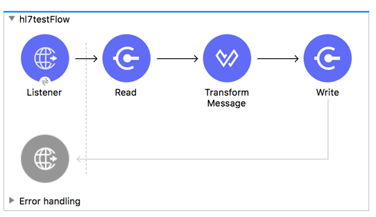
Example: HL7 Studio
The following flow can be loaded from the XML that follows.
<?xml version="1.0" encoding="UTF-8"?>
<mule xmlns:ee="http://www.mulesoft.org/schema/mule/ee/core"
xmlns:hl7="http://www.mulesoft.org/schema/mule/hl7"
xmlns:http="http://www.mulesoft.org/schema/mule/http"
xmlns="http://www.mulesoft.org/schema/mule/core"
xmlns:doc="http://www.mulesoft.org/schema/mule/documentation"
xmlns:xsi="http://www.w3.org/2001/XMLSchema-instance"
xsi:schemaLocation="http://www.mulesoft.org/schema/mule/core
http://www.mulesoft.org/schema/mule/core/current/mule.xsd
http://www.mulesoft.org/schema/mule/http
http://www.mulesoft.org/schema/mule/http/current/mule-http.xsd
http://www.mulesoft.org/schema/mule/hl7
http://www.mulesoft.org/schema/mule/hl7/current/mule-hl7.xsd
http://www.mulesoft.org/schema/mule/ee/core
http://www.mulesoft.org/schema/mule/ee/core/current/mule-ee.xsd">
<http:listener-config name="HTTP_Listener_config"
doc:name="HTTP Listener config" >
<http:listener-connection host="localhost" port="8081" />
</http:listener-config>
<hl7:config name="HL7_Extension_Config" doc:name="HL7 Extension Config" identKeys="true">
<hl7:schemas >
<hl7:schema value="/hl7/v2_5_1/ADT_A05.esl" />
<hl7:schema value="/hl7/v2_5_1/ADT_A01.esl" />
</hl7:schemas>
</hl7:config>
<flow name="hl7testFlow" >
<http:listener doc:name="Listener" config-ref="HTTP_Listener_config" path="/hl7"/>
<hl7:read doc:name="Read" config-ref="HL7_Extension_Config"/>
<ee:transform doc:name="Transform Message" >
<ee:message >
<ee:set-payload ><![CDATA[%dw 2.0
output application/java
---
{
Delimiters: payload.Delimiters,
Id: payload.Id
}]]></ee:set-payload>
</ee:message>
</ee:transform>
<hl7:write doc:name="Write" config-ref="HL7_Extension_Config"/>
</flow>
</mule>xmlSet Your HL7 Identification in XML
You can configure the Message Header (MSH) application and facility identification for you and your trading partner on the HL7 EDI connector configuration.
The values you set are used when writing HL7 messages to supply the namespace ID, universal ID, and universal ID type, and are verified in receive messages. If you don’t want to restrict incoming messages you can leave these blank, and set the values for outgoing messages on the write operation or the actual outgoing message. Values set on the write operation override the connector configuration, and values set directly on the message override both the connector configuration and any values set on the write operation.
-
Self identification parameters identify your side of the trading partner relationship.
Self identification parameters:
appNamespaceIdSelf="<value>" appUniversalIdSelf="<value>" appUniversalIdTypeSelf="<value>"text -
Partner identification parameters identify your trading partner.
Partner identification parameters:
appNamespaceIdPartner="<value>" appUniversalIdPartner="<value>" appUniversalIdTypePartner="<value>"text
Set Parser Options
You can set the following options if needed:
| XML Value | Visual Studio Option |
|---|---|
eventMessageMap="/hl7/v2_5_1/event-message.yaml" |
Event and message to message structure map path (required if using multiple message structures, unless the MSH-09 and MSG-03 message structure values are always present in the received messages). |
genericExtensionPattern="Z.." |
Java regular pattern for generic extension segment names (to allow handling of extension segments as maps of field values). |
invalidCharacterInValueFail="true" |
Fail when an invalid character is in a value. |
missingRequiredValueFail="true" |
Fail when a required value is missing. |
processingId="PRODUCTION" |
Required processing ID (to specify a particular processing ID required on receive messages, such as |
segmentOutOfOrderFail="true" |
Fail when a segment is out of order in a message. |
unknownSegmentFail="true" |
Fail when an unknown segment is in a message. |
unusedSegmentPresentFail="true" |
Fail when an unused segment is included in a message. |
validateHL7Version="true" |
Validate HL7 Message Version. |
valueLengthErrorFail="true" |
Fail when a value length is outside an allowed range. |
wrongSegmentsRepeatsFail="true" |
Fail when there are too many repeats of a segment. |
wrongValuesRepeatsFail="true" |
Fail when there are too many repeats of a value. |
Set Your Schema Locations
You can configure schema locations in the Anypoint Studio XML view.
In Anypoint Studio, click Configuration XML to switch to the XML view and modify your HL7 EDI configuration to include a list of all the schemas to include by adding an <http://edischema[edi:schema]> element for each document type:
<hl7-edi:config name="HL7_EDI__Configuration" identKeys="true" doc:name="HL7 EDI: Configuration">
<hl7-edi:schemas>
<hl7-edi:schema>hl7/v2_6/ADT_A01.esl</hl7-edi:schema>
</hl7-edi:schemas>
</hl7-edi:config>xmlAfter you create a global element for your HL7 EDI, configure the message structure, operations, and acknowledgments.
HL7 Message Structure
The HL7 connector reads and writes HL7 documents into or from a canonical ER7 message structure. This structure is represented as a hierarchy of Java Maps and Lists, which can be manipulated using DataWeave or code. Each transaction has its own structure which is defined in the schemas.
The HL7 message contains the following keys:
| Key name | Description |
|---|---|
ACK (read only) |
ACK message generated in response to the input data. The MSA-01 acknowledgment code value is based on the parser configuration settings. To send an acknowledgment, see the Sending Acknowledgments section. |
Data (read or write) |
Wrapper for message data, with a key matching the message structure ID value linking to the actual data. This allows different messages to be included in the metadata and handled in DataWeave mappings. |
Delimiters (read or write) |
The delimiters used for the message. The characters in the string are interpreted based on position, in the following order: (component separator), (repetition separator), (escape character), (subcomponent separator). |
Errors (read only) |
A list of errors which are associated with the input message. See the HL7Error structure description in the Reading and Validating HL7 Messages section below. |
Id |
Message structure ID. |
MSH (read only) |
Link to received MSH segment data. |
Name (read only) |
Message structure name. |
Individual messages have their own maps, with keys matching the segments of the message. For instance, an ACK message would use the message structure ID ACK, and the data for the ACK message sent or received would be present as an ACK value in the Data map. The ACK message is itself a map, and the segments and groups of the message are represented as maps (in the case of singleton instances) or lists of maps (for repeating instances) with positional keys.
There are two special cases where generic handling is used for data not included in a schema definition. The first is for HL7 values of the varies type. Since these values may consist of any structure of components and subcomponents, and may be repeated, the parser uses a list of maps representation for each varies type. The keys in each map are generated as the value is parsed, matching standard HL7 value names with two digits used for each nesting level.
So a simple text value for an OBX-05 Observation Value field, for instance, would just use the key OBX-05 in a map. If there are two components present, they use keys OBX-05-01 and OBX-05-02.
Extension segments with tags that match a pattern configured under parser options are similar in structure to the varies values, with the exception of only being within a single map for the entire segment.
The maps containing extension segment data are added to the basic message map in lists with the key ExtensionSegs. In addition to the actual extension segment data, the map for the extension segment contains two other keys:
| Key | Description |
|---|---|
Ident |
The extension segment identifier (tag). |
Position |
The position of the segment within the message structure, as a two digit string. This is the same as the position of the immediately preceding defined segment, as defined in the schema. If a ZVN extension segment is used following the EVN segment in an ADT_A01 message structure, the ZVN is at position 03). |
If extension segments are used in nested groups, the list containing those segments are included in the map representing that group. Extension segments are ordered by position in the lists created by the parser, and must also be ordered by position when writing.
Sending Acknowledgments
An ACK (acknowledgement) message is an HL7 message that lets you acknowledge to a message sender that your application has received a message. ACK messages are the same as writing any other HL7 message, except you set the ACK message to what was generated during the read operation as the output message under a Data key.
For example:
<hl7-edi:read config-ref="HL7_EDI__Configuration1" doc:name="HL7 EDI"/>\
...
<dw:transform-message doc:name="Create Outgoing Message">
<dw:set-payload><![CDATA[%dw 1.0
%output application/java
---
{
Name: "ACK",
MSH: payload.ACK.MSH,
Id: "ACK",
Data: {
ACK: payload.ACK
}
}]]></dw:set-payload>
</dw:transform-message>
<hl7-edi:write config-ref="HL7_EDI__Configuration" messageStructure="InMessage" doc:name="ACK"/>
...
<file:outbound-endpoint responseTimeout="10000" doc:name="File" path="output" outputPattern="ack.edi"/>xmlThe generated ACK messages have MSH data set up for sending back to the sender of the original message, so you don’t need to change anything in the data to perform the send.
If you include an ACK message schema in your configuration, that schema is used to both receive ACK messages and generate ACK messages. If you don’t specify an ACK schema, the standard hl7/v2_5_1/ACK.esl schema is used by default.
Reading and Validating HL7 ER7 Messages
To read an HL7 message:
-
Search the palette for HL7 EDI and drag the HL7 EDI building block into a flow.
-
From the properties view, select the connector configuration you created previously and select the
Readoperation.This operation reads any byte stream into the structure described by your HL7 schemas.
HL7 EDI validates the message structure when read. Message validation includes checking the syntax and content of the MSH and all component segments of the message. Normally errors are logged, accumulated, and reported in the generated ACK message provided in the generated data structure. All messages, whether error free or with non-fatal errors, are passed on for processing as part of the output message Map. Errors reading the input data can throw exceptions.
Error data entered in the receive data map uses the HL7Error class, a read-only JavaBean with the following properties:
| Property | Description |
|---|---|
|
Zero-based index within the input of the segment causing the error |
|
Flag for a fatal error, meaning the associated message was rejected as a result of the error |
|
Enumeration for the different types of errors defined by the HL7 standards (ERR-3 values) |
|
Error code, as defined by the HL7 standard for the indicated type of error |
|
Text description of the error |
The Read operation returns error data as an optional list with the Errors key.