99%
High Availability and Disaster Recovery
High availability (HA) and disaster recovery (DR) strategies protect your Mule applications from downtime caused by infrastructure failures, disasters, or maintenance. Deploy Mule runtime in clustered topologies, configure active-active or standby environments, and define Service Level Agreements (SLAs) to meet your uptime requirements. Mule clustering provides automatic failover and shares transient state across nodes to ensure continuous operation.
Planned or unplanned, infrastructure and application downtime can come at any time, from any direction, and in any form. The ability to keep an organization operational during a technology outage, facility destruction, loss of personnel, or loss of critical third party services is critical to preventing irreversible damage to a business. With the increasing global shift to e-commerce models and their reliance on 24/7 application uptime, high availability (HA) and disaster recovery (DR) impact the financial health of organizations.
This table shows how even the least amount of downtime can add up to negatively affect an organization:
| Percentage Uptime | Percentage Downtime | Downtime Per Week | Downtime Per Year |
|---|---|---|---|
1% |
1.68 hours |
3.65 days |
|
99.9% |
0.1% |
10.1 minutes |
8.75 hours |
99.99% |
0.01% |
1 minute |
52.5 minutes |
99.999% |
0.001% |
6 seconds |
5.25 minutes |
High Availability Versus Disaster Recovery
-
High availability (HA) - The measure of a system’s ability to remain accessible in the event of a system component failure. Generally, HA is implemented by building multiple levels of fault tolerance and load balancing capabilities into a system.
-
Disaster recovery (DR) - The process by which a system is restored to a previous acceptable state, after a natural (flooding, tornadoes, earthquakes, fires) or man-made (power failures, server failures, misconfigurations) disaster.
While they both increase overall availability, the notable difference is that with HA there is generally no loss of service. HA retains the service and DR retains the data, but with DR, there is usually a slight loss of service while the DR plan executes and the system restores.
Deploying Mule for HA and DR Strategies
You can deploy the Mule runtime in many different topologies to address your HA and DR strategies. One method is through the use of high availability clustering, which provides basic failover capability for Mule.
When the primary Mule runtime becomes unavailable, for example, because of a fatal JVM or hardware failure or it’s taken offline for maintenance, a backup Mule runtime immediately becomes the primary node and resumes processing where the failed instance left off.
After a system administrator recovers a failed Mule runtime server and puts it back online, that server automatically becomes the backup node.
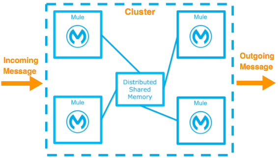
Seamless failover is made possible by a distributed memory store that shares all transient state information among clustered Mule runtimes, such as:
-
SEDA service event queues
-
In-memory message queues
As you build your Mule application, it’s important to think critically about how best to architect your application to achieve the desired availability, fault tolerance, and performance characteristics.
Creating Effective SLAs
The Service Level Agreement (SLA) outlines the specific definition of what is acceptable.
The basic definition of high availability is that the service is up and functioning and properly processing requests and responses. This doesn’t mean the service always operates at full capacity. Systems designed with high availability protect against interruptions and prevent outages from happening in the first place. The SLA identifies expectations for all stakeholders.
SLA Requirements:
-
Single points of failure are eliminated
-
Traffic/requests are redirected/handled
-
Detection of failures
For example a basic service may have these SLAs:
-
The normal operation of the service handles 1000 transactions per sec with 1 sec response times.
-
The total downtime per year is 0.5% or 1.83 days.
-
Minimal acceptable service impact level is 100 transactions per sec with 1 sec response times for a period of 2 hours a week.
See also:
High Availability Options
You can achieve high availability through the use of clustering and load balancing of the nodes. Depending on the defined SLA, four HA options are possible with Mule:
| Often these options are associated with a disaster recovery strategy. |
Cold Standby
| Diagram | Description | Downtime |
|---|---|---|
|
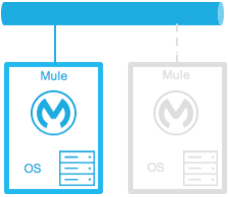
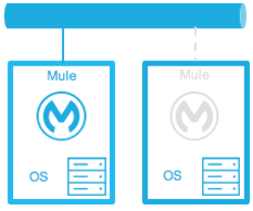
The Mule environment is installed and configured, however one or more operating systems aren’t running. This can be a backup of a production system/virtual machine. The environment of the operating system plus the Mule runtime has been started after an outage is detected. |
Some - The time it takes to start the environment and direct traffic. |
Warm Standby
| Diagram | Description | Downtime |
|---|---|---|
|
The Mule environment is installed and configured. However the Mule runtimes aren’t running; only the operating systems. The Mule runtime instance is started after an outage is detected. |
Little - The time it takes for the Mule runtime instances to start and to route traffic to the environment. |
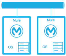
Hot Standby - Active-Passive
| Diagram | Description | Downtime |
|---|---|---|
|
The Mule environment is installed, configured, and fully running. However, it’s not processing requests until an outage is detected. |
Minimal to none - The time to route traffic to an environment. |
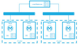
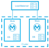
Active-Active
| Diagram | Description | Downtime |
|---|---|---|
|
Load Balanced clustered environments There are two or more Mule environments (each environment has its own cluster) that are fully operational. The load balancer is directing traffic to all of the environments. |
None - There is no service downtime. |
|
Load Balanced single clustered environment There are two or more Mule environments, however they’re part of the same clustered environment. To achieve this scenario, the network latency between environments must be less than 10ms. |
None - There is no service downtime. |
High-Availability for On-Premises Deployment Models
|
When you deploy an application to an on-premises Mule cluster by using Runtime Manager, deployment artifacts are staged to cluster nodes sequentially. Sequential staging doesn’t guarantee that the application starts on one node before startup begins on another. Application startup and readiness across cluster nodes aren’t ordered and can overlap. |
Active-Active Clustering Deployment Model
It’s plausible that two nodes in a clustered or load balanced environment can support 1,500 TPS with one-second responses. In this state, the normal operation of the SLA is being met. If a node fails, the service is impacted. However, the impact doesn’t breach the SLA because the node is able to handle 700 TPS with one-second responses; well above the agreed upon acceptable impact level.
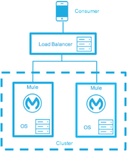
Distribute the load evenly among multiple Mule nodes:
-
All nodes offer the same capabilities
-
All nodes are active at the same time.
Costs
Vary depending on SLA requirements. This model needs two nodes to satisfy SLA. If the SLA’s acceptable service impact changes to the terms stated in the normal operations then at a minimum the environment needs three nodes to accommodate one node failure. More nodes may be required depending on the probability of not having at least two nodes running.
Active-Active Clustering Fault Tolerance Deployment Model
Fault tolerance means a failure within the system doesn’t impact the service at all. This differs from high availability as service impact and downtime are tolerated.
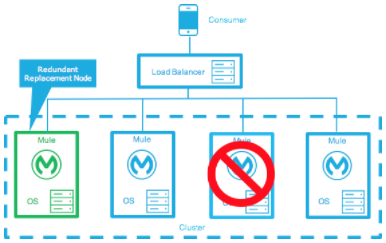
Fault tolerance differs from high availability by providing additional resources that allow an application to continue functioning after a component failure without interruption. Fault tolerant environments are more costly than high available environments.
The degree of fault tolerance requires the probability of system failures. Take the SLA example highlighted under high availability and make the minimal acceptable service impact level match the normal operation requirement.
The new overall SLA now requires the system to be able to handle 1000 transactions per sec with 1 sec response times, zero downtime, and zero service impact.
If the probability of having more than 1 node fail is low then the architecture would simply require 3 nodes. However, if the probability of more than 1 node is higher than acceptable, more than 3 nodes are required to accommodate multiple failures.
Costs
More costly due to the required redundancy in order to meet defined SLA.
Zero Downtime Deployment Model
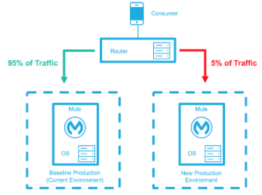
The goal is to make changes to the environment without impacting the SLAs; including upgrading infrastructure and the applications running on the infrastructure. Typically zero downtime deployments leverage a side-by-side deployment, where the old and new coexist for a short period of time. This is in contrast to an in-place deployment where the service may experience reduced capacity to complete downtime.
Gartner defines continuous operations as “those characteristics of a data-processing system that reduce or eliminate the need for planned downtime, such as scheduled maintenance. One element of 24-hour-a-day, seven-day-a-week operation”.
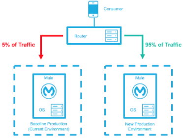
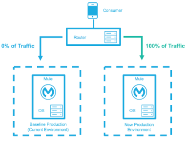
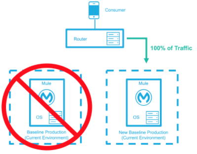
The baseline production environment is the current operating environment. A new environment is created with the changes (upgraded runtimes, configurations, new applications). A small percentage of traffic flows to the new environment and increases as the confidence in the new environment increases. The baseline production environment continues its use until the new environment is fully operational (it’s handling 100% of the traffic). After the new environment is accepting all traffic, it becomes the new baseline production environment and the previous baseline production environment terminates.
This example is assuming each environment is using the same number of Mule runtimes and cores. It’s plausible that the new environment has either more or fewer Mule runtimes and cores than the baseline environment.
| Deployment Step | Diagram |
|---|---|
New Production Environment deployed and a small percentage of traffic is routed to new environment. |
|
Confidence in the new environment continues to increase and more traffic is routed to it. |
|
All traffic has been routed to the new environment. |
|
All traffic has been routed to the new environment, which has been promoted to the baseline production environment; the previous baseline environment has been terminated. |
|
Costs
This deployment method may temporarily add capacity to the service (can be a few minutes, hours, or days).
Disaster Recovery
How quickly can your company get back to work after an IT emergency?
Disaster recovery (DR) is the process by which a system is restored to a previous acceptable state, after a natural or man-made disaster. For DR, use measurable business requirements such as Recovery Time Objective (RTO) and Recovery Point Objective (RPO), to drive your DR plan.
Disaster recovery is about your Recovery Point Objective (RPO) and your Recovery Time Objective (RTO). RPO is the "point" that you return to after an IT disaster. For example, if you back up the system every 24 hours, your RPO is a maximum of the past 24 hours. RTO, on the other hand, is how quickly you can restore to your RPO and get back to business. This includes activities like the time it takes to get your spare equipment to start running your backups if your primary equipment isn’t working.
System backups are a major component of a solid disaster recovery program. There are three types of recovery: cold, warm, and hot.
| Term | Definition | Example |
|---|---|---|
Recovery Time Objective (RTO) |
How quickly do you need to recover this asset? |
1 min? 15 min? 1 hr? 4 hrs? 1 day? |
Recovery Point Objective (RPO) |
How fresh must the recovery be for the asset? |
Zero data loss, 15 mins out of date? |
For deployment-specific disaster recovery details, see:
Keep Integrations Stateless
As a general design principle it’s important to ensure integrations are stateless in nature. This means that no transactional information is shared between various client invocations or the executions (in case of scheduled services). If the middleware needs to keep some data because of a system limitation, it should be persisted in an external store such as a database or a messaging queue. It shouldn’t be stored within the middleware infrastructure or memory. It’s critical to note that as the system scales, especially in the cloud, the state and resources used by each worker/node should be independent of the other workers. This model ensures better performance, scalability, and reliability.
